Main Switchboard (MSB)
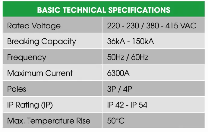
The Main Switchboard (MSB) is the primary power distribution panel that supplies electricity to the entire low-voltage electrical system of a facility.
Metal enclosure: 1.5 mm – 2.5 mm thick sheet steel, powder-coated finish.
Modular design: Each module is divided into multiple separate compartments (fixed or withdrawable type), enabling easy installation, transportation, and future expansion.
Designed with internal segregation in Form 1, Form 2a, Form 2b, Form 3a, Form 3b, Form 4a, and Form 4b configurations, in accordance with International Electrotechnical Commission IEC 61439-1 standard.
ATS Panel
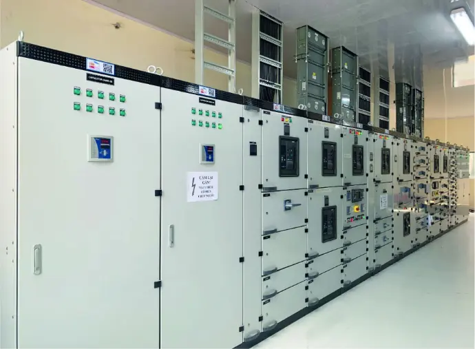
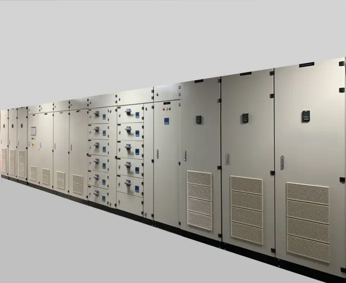
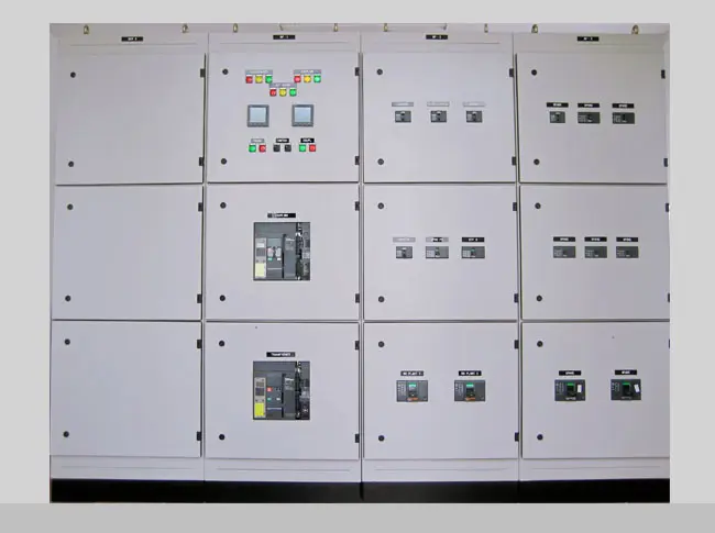
The Automatic Transfer Switch (ATS) system is an automatic power transfer system that, in the event of a utility power failure (main source), automatically starts the generator (backup source) and transfers the electrical load to supply the consumers.
When the utility power is restored, the system automatically transfers the load back to the main supply and shuts down the generator. The transfer time can be adjusted.
In addition, the Automatic Transfer Switch (ATS) panel is typically equipped with protection functions against electrical faults in both the utility and generator supply, such as phase loss, neutral loss, over/under voltage (adjustable), overcurrent, and ground fault.
The ATS panel operates in both manual and automatic modes, providing convenience for testing and operation.
It can be integrated with the Main Switchboard (MSB) and reactive power compensation capacitor bank panel.
Distribution Board (DB)
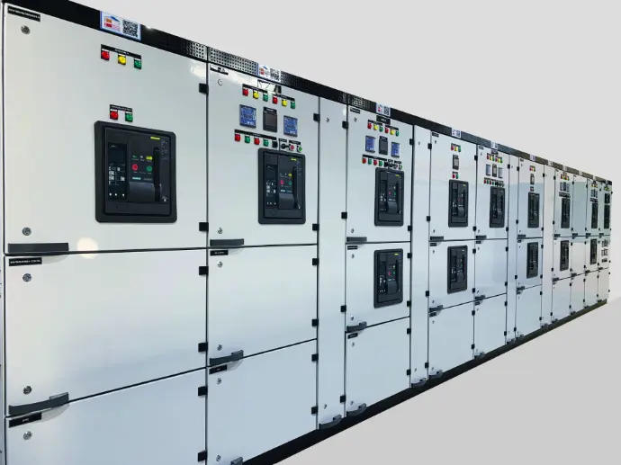
The Distribution Board (DB) is a sub-distribution panel that supplies electrical power to each area within a facility. It is installed downstream of the Main Switchboard (MSB) and upstream of the final loads, providing power distribution to different zones of the building or to groups of equipment in a factory.
Metal enclosure: 1.5 mm – 2.0 mm thick sheet steel, powder-coated finish.
Designed with internal segregation in Form 1, Form 2a, Form 2b, and Form 3b configurations, in accordance with International Electrotechnical Commission IEC 61439-1 standard.

Distribution Board (DB)
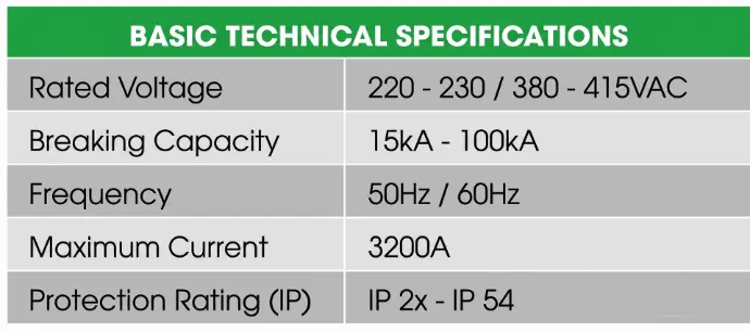
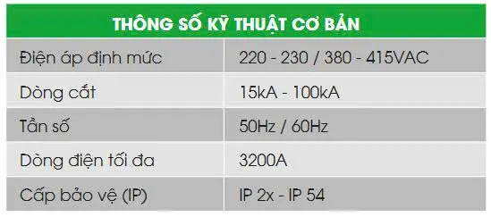
The Distribution Board (DB) is a sub-distribution panel that supplies electrical power to each area within a facility. It is installed downstream of the Main Switchboard (MSB) and upstream of the final loads, providing power distribution to different zones of the building or to groups of equipment in a factory.
Metal enclosure: 1.5 mm – 2.0 mm thick sheet steel, powder-coated finish.
Designed with internal segregation in Form 1, Form 2a, Form 2b, and Form 3b configurations, in accordance with International Electrotechnical Commission IEC 61439-1 standard.
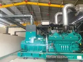
Synchronization Panel
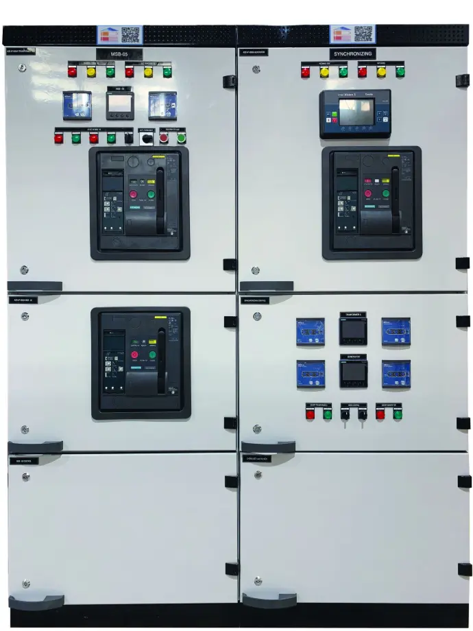
The Synchronization Panel is designed to synchronize two or more generators. In the event of a utility power failure, the standby generators will automatically start, synchronize, and share the load with each other. In addition, the synchronization panel is capable of load monitoring and automatically determines the number of generators required to operate based on the load demand.
The Synchronization Panel is typically designed with multiple compartments, including a main control cabinet and individual generator control sections for each unit. The system supports both automatic and manual operation modes. It is integrated with monitoring and alarm functions, displaying warnings via LCD screen, indicator lights, or audible alarms. The panel also allows remote monitoring and control, and it can store alarm history to assist operators in system supervision and maintenance.
Equipped with advanced synchronization controllers such as ComAp, Woodward, and Deep Sea.
Capacitor Bank Panel
The capacitor bank panel is used to improve the power factor (cos φ) by utilizing capacitor banks as a source of reactive power compensation.
The capacitor bank panel typically consists of multiple capacitor steps, each controlled by a contactor. Switching the contactors ON or OFF changes the number of capacitor banks operating in parallel. A power factor controller monitors the system power factor and controls the switching of the contactors accordingly, thereby adjusting the overall power factor of the electrical network.
Reactive power compensation capacitor bank panels are used in electrical systems with highly inductive loads. They are typically installed in electrical rooms or substation areas of industrial facilities such as factories, high-rise buildings, offices, apartment complexes, and hospitals.
Our capacitor bank panels can be operated in either Manual or Automatic mode.
The panel can be equipped with detuned reactors to reduce harmonic distortion or other components depending on customer requirements. It is designed for efficient heat dissipation and is fitted with ventilation fans for cooling, as well as anti-condensation heaters to reduce humidity inside the enclosure.

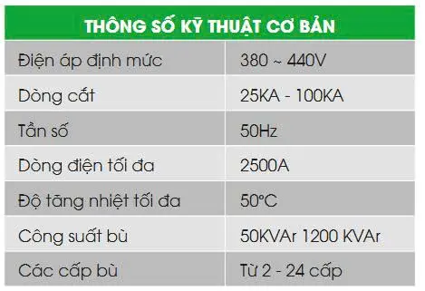
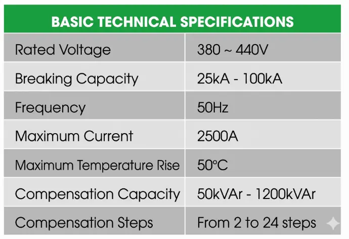
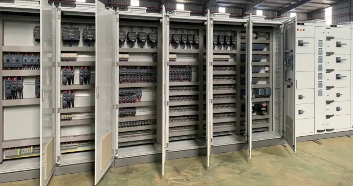
Capacitor Bank Panel
The capacitor bank panel is used to improve the power factor (cos φ) by utilizing capacitor banks as a source of reactive power compensation.
The capacitor bank panel typically consists of multiple capacitor steps, each controlled by a contactor. Switching the contactors ON or OFF changes the number of capacitor banks operating in parallel. A power factor controller monitors the system power factor and controls the switching of the contactors accordingly, thereby adjusting the overall power factor of the electrical network.
Reactive power compensation capacitor bank panels are used in electrical systems with highly inductive loads. They are typically installed in electrical rooms or substation areas of industrial facilities such as factories, high-rise buildings, offices, apartment complexes, and hospitals.
Our capacitor bank panels can be operated in either Manual or Automatic mode.
The panel can be equipped with detuned reactors to reduce harmonic distortion or other components depending on customer requirements. It is designed for efficient heat dissipation and is fitted with ventilation fans for cooling, as well as anti-condensation heaters to reduce humidity inside the enclosure.
Motor Control Center (MCC)
The Motor Control Center (MCC) is a power distribution and motor control panel that operates motors according to a designed control scheme, using devices such as variable frequency drives (VFDs), soft starters, direct-on-line (DOL) starters, and star-delta starters.
Metal enclosure: 1.5 mm – 2.0 mm thick sheet steel, powder-coated finish.
Modular design: Each module is divided into multiple separate compartments, allowing easy installation, transportation, and future expansion.
Designed with internal segregation in Form 1, Form 2a, and Form 2b configurations, in accordance with International Electrotechnical Commission IEC 61439-1 standard.
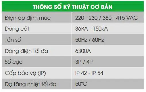
Motor Control Center (MCC)
The Motor Control Center (MCC) is a power distribution and motor control panel that operates motors according to a designed control scheme, using devices such as variable frequency drives (VFDs), soft starters, direct-on-line (DOL) starters, and star-delta starters.
Metal enclosure: 1.5 mm – 2.0 mm thick sheet steel, powder-coated finish.
Modular design: Each module is divided into multiple separate compartments, allowing easy installation, transportation, and future expansion.
Designed with internal segregation in Form 1, Form 2a, and Form 2b configurations, in accordance with International Electrotechnical Commission IEC 61439-1 standard.